Introduction
Latency critical nature of computer vision applications motivates the use of the Edge computing paradigm where compute and storage are done at the Edge of the network close to the camera. The main motivation behind the design of our system is to make available real-time video frames from multiple cameras to Deep Learning surveillance applications at the Edge for analytics, detection, and prediction of a diverse set of events/objects while being scalable. A subset of such applications includes, pedestrian safety guidance, road accident prediction, drunken driver detection and crime detection in public spaces.

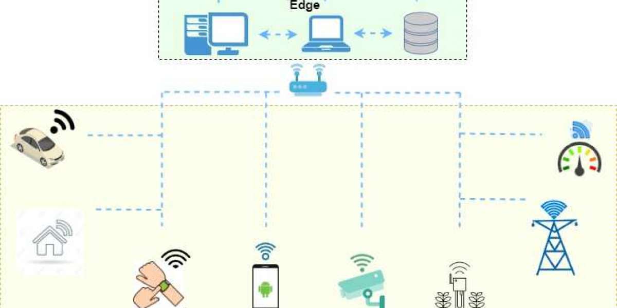
As shown in Figure, the physical model of our system consists of multiple embedded boards equipped with video cameras communicating to an Edge server through WiFi (802.11ac) wireless routers. The cameras monitor video scenes from different angles in a particular area of interest (e.g., traffic intersection, parking lot). The camera nodes are assumed to have limited compute and storage resources compared to the Camera nodes. The camera nodes are Jetson TX2 boards and the Edge server is a laptop furnished with GPU. Jetson TX2 boards connect to the access point through the 802.11ac WiFi link. Our workload consisted of several pedestrian car accident surveillance videos from YouTube. These videos are obtained from real-life incidents where the pedestrian is struck by an automobile. The overall goal of our multi-camera Edge vision system in this case would be to provide sufficiently early warning to pedestrians and drivers to avoid potential accidents.
Characterizing wireless latency at the Edge
We initially characterized the image transfer latency from camera node to the Edge server, for different image sizes, with the camera node at different distances from the access point. Figure below shows the variation in latency (plotted on the y-axis), at different image sizes (plotted on the y-axis).

From these measurements, we note that the latency approximately increases linearly with size. This result suggests that for camera nodes at fixed locations, the latency can be tuned by varying the size of the image.
To study the impact of interference when two camera nodes are transmitting simultaneously, we set up the camera node under test at a distance of 5 meters away from the access point, and the second camera node at a distance of 3 meters. Both camera nodes continuously transmit image frames to the Edge server. Figure below shows that the interference causes the test camera node to a suffer a latency increase as high as 164 %.

As seen from this experiment, the latency for image frame transfer from camera node to Edge server varies dramatically in an unpredictable communication environment at the Edge. Since many camera nodes might be operating in a given Edge vision system, counter measures have to be taken to mitigate this increase in latency due to interference for latency critical Edge vision applications.
Approximate computing for latency control
As seen in our experimental evaluation of latency in previous plot, channel interference from other camera nodes can cause channel latency to increase. We also note that for fixed camera node locations, tuning the image size is a potential means to control latency. However, reducing the information content in the images could make them unusable for object/event detection/prediction vision applications. Hence we explore potential modifications that can be done on images through which we can modify the image content and thus vary the image sizes. We call these modifications as tuning knobs for images. We present five such tuning knobs - resolution, color space modifications, blurring, choice of detection techniques, and choice of frame differencing techniques. We then study the impact of these tuning knobs on accuracy for an object detection machine vision benchmark.
Machine vision benchmark - Object detection
Popular object detection Deep Learning algorithms include Faster R-CNN, You Only Look Once (YOLO) and Single Shot Detectors (SSDs). We chose the SSD model since it is suited to resource constrained devices. We used pre-trained MobileNet model, specifically designed for embedded vision applications, trained using Caffe-SSD framework. The model detects objects such as cars, persons and plants in the original image frames as well as in the modified image frames (all knobs varied individually). We calculate the True Positive Rate (TPR) for each setting for all the knobs (including the unmodified frames) based on the manually verified ground truth. TPR measures the actual positives that are identified as such. Figure below visually shows the impact of applying tuning knobs color space modification and blurring to a video frame from the pedestrian accident videos from YouTube.

Characterizing Image Size Vs. Application Accuracy
We now systematically evaluate the impact of the tuning knobs on image size and application accuracy (TPR). Figure below shows the plot of the True Positive Rate (TPR) of detected objects vs. image size for the object detection application. Note that higher TPR indicates higher accuracy.

The relationship between TPR and image size is complex since multiple image size values (obtained from different combinations of knob settings) map to similar TPR values. In the Figure given below it is observed that images greater than 400 KB, have maximum TPR above 0.8 and median TPR above 0.7. For images below 400KB size, we see that the median TPR decreases below 0.6, but the presence of knobs with TPR close to 1.0 makes the images in this size range usable for the object detection application. This key observation enables transmission of smaller sized images with almost similar TPR as the original image from the camera node to the Edge server, in the presence of channel interference. We exploit this observation in the design of the latency controller.
Design of Control Strategy
The camera nodes need to be able to provide image frames within the latency and accuracy levels (TPR) requested by the vision applications executing on the Edge server. Since the dependence of application accuracy is complex, we have two options (1) Use a sophisticated machine learning model to predict the accuracy and knob combinations for an input image size, or (2) Use a look up table that stores the image size and application accuracy for all knob combinations. We chose the lookup table approach since the total knob combinations of the 5 knobs results in 2500 values, a small number easily stored in memory. These can be initially characterized andvquickly looked up using a primary hashtable with the image size as the key, and the candidate accuracies as the value. A secondary hashtable uses the accuracy as the key and the knob settings as the values.
The control algorithm has two steps. In Step 1, the error (error and integral of error for Proportional-Integral control) between the observed the the specified latency is used to determine the image size that can potentially satisfy latency requirements. The almost linear dependence of latency on image size facilitates an effiicient binary search for the nominal image size. In Step 2, we lookup the primary hashtable with the image size as the key to determine the candidate accuracy values. For the accuracy values that satisfy the application request, the secondary hashtable is used to lookup the knob combinations. The image frames transmitted from camera to Camera node are modified subject to these knob combinations. The latency is measured again at the next sampling interval, and if the error exceeds a preset threshold, Steps 1 and 2 are repeated. If the application requested latency and accuracy are infeasible, the application is notified. At this point, the application has to decide whether to continue operation with relaxed requirements, or send the notification higher up the stack to the user.
Results
We evaluated the control algorithm on the Edge test bed described earlier. The camera node under test and the peer camera node were kept at a distance of 5 m and 3 m from the access point. For the MobielNet-SSD benchmark the application request latency was set at less than 200ms and TPR was set at greater than 0.94. Initially, only the camera node under test was transmitting image frames to the Edge server. The controller was able to satisfy these requirements with a median image size of 1MB. Note that the resulting latency and accuracy exceed the specifications. To study the effectiveness of the controller when the wireless channel is subject to interference, the peer camera node was turned on to transmit images. Figures 8a and 9a show the control action (latency vs. time). Initially the latency increases due to the interference from the peer camera node. However, the controller is able to bring the latency back to the desired value by tuning the image quality knobs, all the while keeping the accuracy under the specified threshold. The controller settling time was measured as 0.63s. Figures below show the resulting plot of image size vs. time for the controller action.

Conclusion and Future Directions
This article demonstrated how latency and accuracy specifications of Edge vision application can be achieved despite the presence of signcant latency variations due to interference in the wireless channel. The control knobs are derived from the approximate computing based observation that a degraded image quality can be tolerated as long as application accuracy requirements are satised. An efficient two-step control algorithm that uses a proportional integral controller, and a hashtable based lookup to dynamically determine the control knob settings based on latancies sampled during operation. Our control approach is scalable since each camera node runs its controller independently. Future extensions of this project include evaluating the approximate control algorithm on other machine vision applications such as object tracking, and studying the impact on interference as nodes are scaled. Another interesting direction is to study the tradeoffs between centralized vs decentralized control.